Harrison Wieting
PHYSICS ENTHUSIAST
DRSSTC1
(Dual Resonant Solid State Tesla Coil)
Basic Specifications
Secondary: 20" winding of 30 AWG on 6" OD PVC form
Resonant Frequency: With topload is 77.64 kHz approx.
Primary: 9 turns of .25" copper tubing with .25" spacing between turns on a 12" diameter helical form tapped at about 6.8 turns for a resonant frequency of 66.5 kHz with an inductance of .018916mH. Inductance at full tap position of 9 turns is 0.029454mH. A table of inductances and frequencies can be seen in the section that covers the primary.
Coupling: About .18
Toroid: four 90 degree PVC elbows 6.5" OD form constructed together for roughly a 20" x 6.5" topload
Feedback: Primary feedback using a current transformer. The CT's are made from two cascaded ferrite toroids with 1:33:33 turns ratio for a 1:1089 ratio (1:1000 approx.) Primary feedback sampling uses a 10ohm burden to allow a .01VA division on the oscilloscope.
Over Current Detection: OCD is set to 850A. I've tested it to 1000A accurately. The OCD network burden resistor is 10 ohms
Power Electronics: 145V from the variac, full-wave rectified and doubled by a pair of 12000uF 200V large electrolytic caps in series for 6000uF 400V.
Bridge: Full-bridge of IXYS IXGN60N60C2D1 IGBT's SOT-227B Package
Control Electronics: OCD (Over Current Detection)/Active Current Limiting. Synchronized Drive Circuitry. External Modulator. Two inverting and two non-inverting UCC mosfet drivers.
Grounding: Secondary is grounded to mains earth or a ground rod. All heatsinks, transformers, strike-rail, and enclosures are grounded to mains earth.
Spark Length: Maximum length to date is 55 inches
The above specifications are experimental. Parameters have been changed around here and there. Final specifications will be posted at a later time.

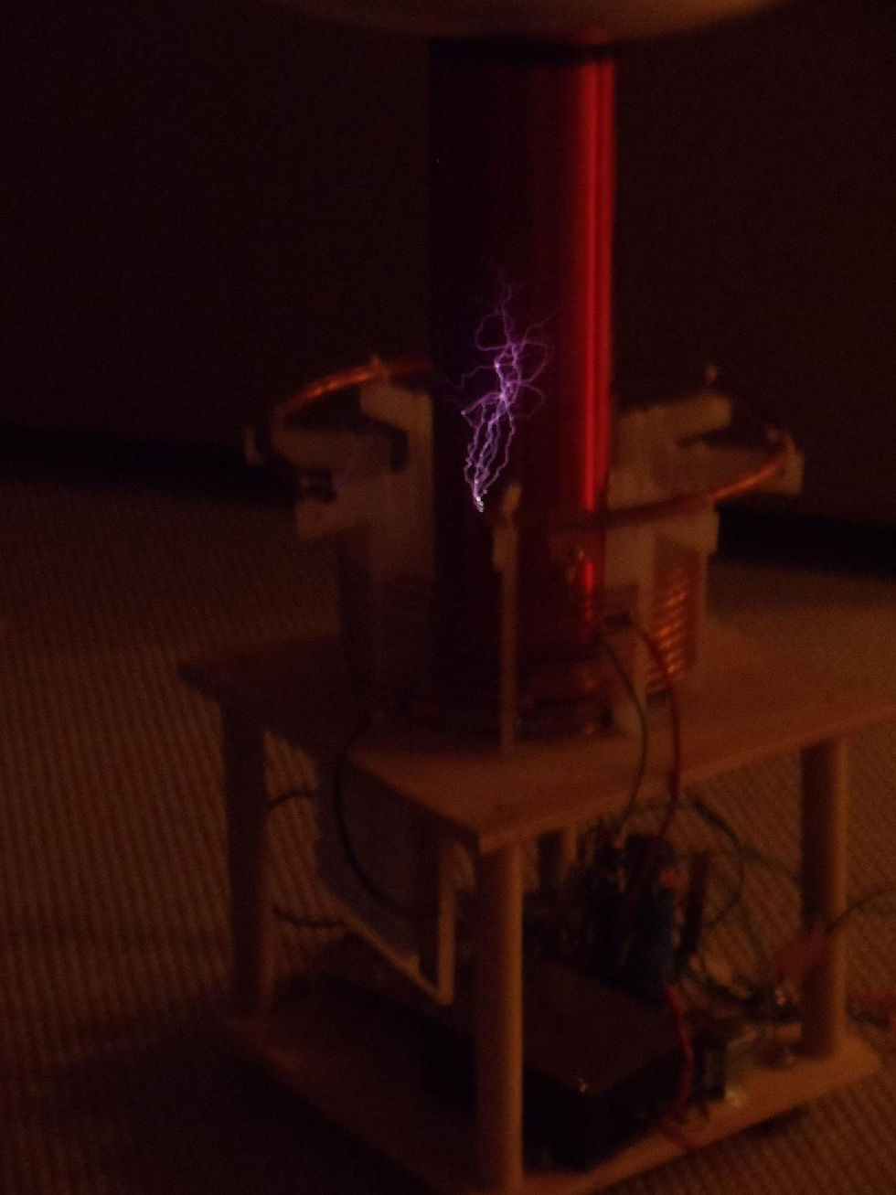
My Drsstc1 showing off pretty arcs.

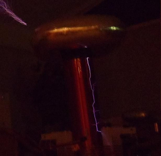
More spectacular sparks. This image was much more focused and came out clear and sharp. You can see me behind my tesla coil command center in the bottom left.
For detailed construction information, visit my DRSSTC design page here.
This page is still being put together, I have A LOT of information, photos, and videos for this project so not all will be posted here. Some photos you see might not actually be a part of the final system, as I have remade this entire system several times in efforts to make everything as quality as I can.

On the left is a picture of the entire coil system ready for first light. There were some initial flaws which required minor changes to the coupling and strike-rail. At first light I was experiencing major strike-rail to secondary arcing. The coupling really had to be finely adjusted to eliminate the racing sparks and flash overs as seen below.
4/15/13 - Another major issue I was having is excessively high primary currents. The primary coil is tuned to exact resonance with the secondary! This is a big NO-NO! But this is how my system seems to run happy. As I detune the primary to compensate for arc loading, currents quickly exceed 1000 amps and things get explosive on the bridge. I have violently blown up 12 IGBT's when trying to detune. More specifically, I cannot detune more that about 5%. At that point current is on the edge of 1000A at about 250-300VDC measure at the DC Bus supply. Also, spark length and overall performance seems to decrease as I detune. My maximum spark length to date is 55" and that is with the primary tuned to about 76-77kHz with OCD set to about 850A. I really have to push the coil and trip the OCD to get 55" ground strike, which I am not comfortable with. I have made many changes and am still experimenting with this coil to reduce the current so I can get some bigger sparks. A full-bridge of the 60N60 transistors should be capable of 80" sparks no problem. I first tried raising the surge imedance ( Z=sqrt(L/C) ) by decreasing primary capacitance to .1999uF ~.2uF. This lowered the primary current significantly and allowed me to achieve arcs over 4 feet long whereas before I could only get 36" max with a primary capacitance of .3uF. One thing I find odd is the low coupling. The coupling had to be changed to about .13 to eliminate racing sparks. A lower coupling means higher currents, so I had to sacrifice the coupling for higher currents. It's odd because this build is a duplicate of Steve Ward's DRSSTC1. The original design parameters of my build are identical to his. Many others have also copied his design and have had great success with it. However, I cannot get this system to run happy with a lower impedance and higher coupling. I recently have been suspicious that my DC Bus supply wiring is creating large inductances on the bridge. This is bad for several reasons. First off, the more inductance on the bridge means nasty voltage spikes in the primary capacitor, and by using a bit of ohms law and RMS equations I can calculate that the RMS currents can reach as high as 180A RMS!! This is UNACCEPTABLE! Normal RMS currents for a system like this would be in the range of 50-70A, 70 is really an upper limit. That being said, I have changed the DC Bus supply layout. The large electrolytics are now mounted directly above the bridge as close as possible. The heavy gauge wiring has also been replaced by .025mm copper buss sheet. Due to the sporadic Michigan weather, I will have to wait to test this new layout when it is not snowing and hailing in the middle of April......
Below are some data tables and videos I've compiled whilst trying achieve best performance. Click images for a larger view.


Oddly, the current signal looks just fine when tuned to the natural frequency of the secondary. Spark lengths in these videos are 41" to 50".
The above table is the original design parameters and does not accurately match the new parameters as of April 2013.
Click images for a closer look and short description

A sneak peak of Primary, Secondary, and MMC parameters.

MIDI modulator

Modulator
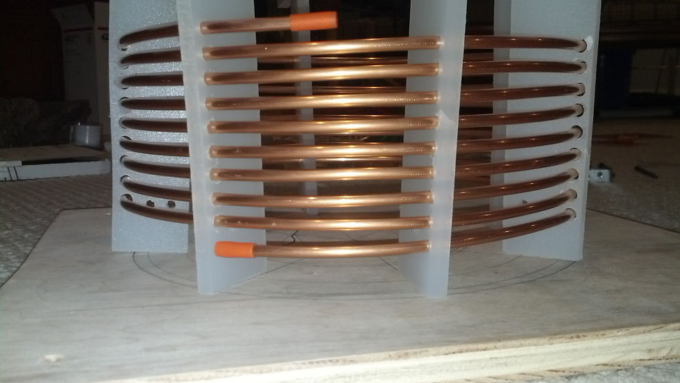
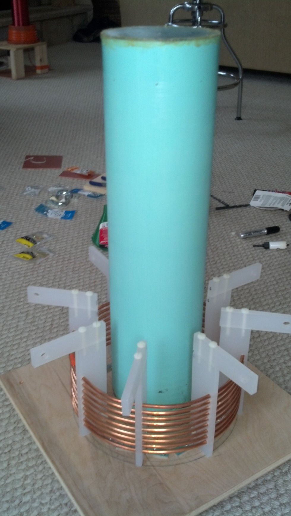
Unmounted Primary
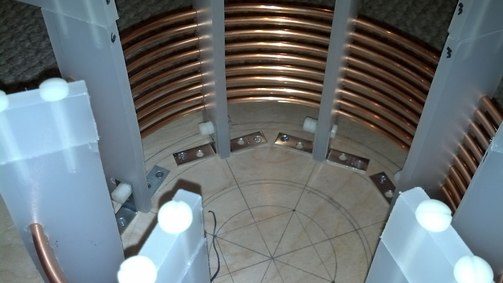
Mounted Primary

Base mount with electronics

a 6x3 MMC using the popular .15uF 2kV CDE for a total of .3uF 6kV

MMC, this will have to be reconstructed before first light

Rise and Fall times under 200ns

Rise and fall times under 200ns

IGBT Gate Waveform!

Differential C-E junction measurement (The green waveform is what we are paying attention to here, not the blue)

Interrupter Pulse at the IGBT gates for starting primary oscillations
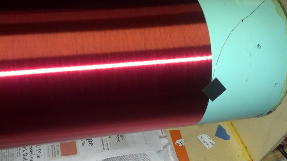
Secondary before winding

Base mount for the sencondary
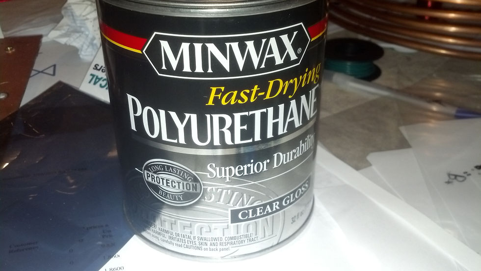
Varnish for the secondary

Enamel for the Secondary

Full bridge

Half-bridge section

GDT

Etched PCB

2nd Generation DRSSTC controller

Toroid

10A 140VAC Variac. The output is actually 145V measured with a DMM

Full wave voltage doubler

Winding Jig
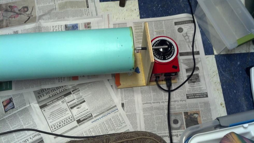
Winding Jig
Almost done

Winding is done
Nice tight winding, no spaces, no overlaps, no scrunches

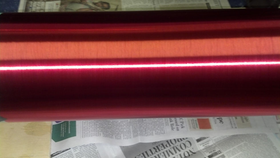
Small space developed. I carefully closed it by nudging the end with my fingernail.

Varnishing

Half varnished
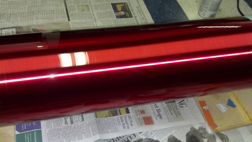
1st coat of varnish is complete!