Harrison Wieting
PHYSICS ENTHUSIAST
SSTC4
Specifications
Secondary: 10" winding of 24AWG on 4" OD cardboard mailing tube form.
Primary: 4 turns of 14AWG stranded insulated wire wrapped tightly around the bottom of the secondary windings.
Toroid: No toroid is necessary. I have 6" x 3" toroids that I have tried, but they make no difference in performance or output
Feedback: Secondary feedback using a current transformer
Power Electronics: 145V from the variac, half-wave rectified and smoothed by a 10uF 400V CDE
Bridge: Half-bridge of IRFP260M mosfets with 5ohm gate resistors
Control Electronics: One inverting and one non-inverting UCC mosfet driver's, with sockets for two more if a full-bridge topology is desired. No On-board modulator. BNC jack for use of an off-board modulator and audio modulation.
Grounding: Secondary is grounded to mains earth
Spark Length: 8-10" at least. Exact length is to be determined.
This SSTC4 is exactly the same as the SSTC3 with respect to the drive circuitry and half-bridge. I split them in two projects because this SSTC4 secondary is a 10" winding with no toroid whereas SSTC3 uses the same 20" secondary and toroid from my previous systems, the primary's are different, and the spark output was much different between the two. It was also easier to showcase them separately. Also, This system can easily be turned into a first generation DRSSTC. All that needs to be done is to create a tuned LC circuit to the same frequency as the secondary. I will probably not do this with the SSTC4 system because the I am too impressed with the results of this system and have no desire to change anything with it. Although I do admit, I am quite interested how the little coil would function as a DRSSTC.
I made the driver board for this SSTC in February of 2013, even more recent then when I started my DRSSTC1 project. This is actually a driver designed to be used for DRSSTC's. The overall performance of this circuit greatly exceeded my expectations. In general, the schematic is almost the same as Steve Ward's MINI SSTC5 which I used for my SSTC1. The major differences are the use of a current transformer instead of an antenna, more robust low voltage power supply, and a more fancy gate drive circuit.
I had to make minor changes to it because the schematic in the book was a bit out of date. First off, I had problems with using a 1k ohm pull down resistor on the UCC's pin 3 (ENA). It was severely messing up my modulator signal, so I simply left it out. This is okay for an SSTC as long as you are careful about how much power you apply to the bridge as well as always making sure that the modulator is turned on before applying power to the driver board or bridge. The reason being that if the modulator is off, while the driver board and bridge is on, then the mosfets will kick in to CW mode (continuous wave) and this can create quite a bit of heating in both the UCC's and mosfets. So always make sure that your modulator is connected and turned on before applying power to the driver board and bridge. If you use this circuit for a DRSSTC then you MUST make sure you use a pull down resistor or ALWAYS have your modulator on first. Otherwise, say goodbye to your expensive IGBT's... Secondly, I left out the on-board modulator. Since I made my own off-board modulator, I didn't have any reason to waste the parts on this circuit, so I just used the BNC jack. I suggest finding a BNC jack that is all metal like the one seen in the image below. This way the cable will always be grounded on the driver board end and help eliminate noise.

Self Resonant Driver Board
Here is the Self-Resonant Driver Board. I made my own PCB for this circuit and thanks to the free artwork on EVR website, it is almost an exact copy. Notice I only have one pair of UCC's installed because I'm using this board to drive a half-bridge rather than a full-bridge. The blue core is an epoxy coated ferrite core by EPCOS, material N87. It is a 1:70 turns ratio of 24AWG. This is a perfect transformer for CT's and GDT's.
Specific Inductance (AL) = 2940 +-25%
Initial Permeability (ui) = 2200
Dimensions (mm) + 36.0 x 23.0 x 15.0
Manufacturer's Part Number = B64290L0674X087
The GDT RTN second to the bottom does not have a screw mount because it did not have any screw threads! Too late now, I don't feel like desoldering it.


Modulator
This is the Modulator I use for all of my tesla coil's that I currently have. It is based on Steve Ward's DRSSTC Interrupter with Burst Mode. Mine is different in the respect that I use a fancy fiber optic driver system using a mosfet driver and the popular HFBR-1412TZ, as well as BNC for a more universal adaptation. I also use an AND Gate from a SN74HC08N Quad AND Gate for fancy LED indication. Steve's schematic show's the burst mode using a SPST (single pole single throw) ON-OFF type switch whereas I use a SPDT (single pole double throw) ON-ON switch. For some reason I never was able to get the burst mode circuit to work properly with the ON-OFF switch.
Half-Bridge Section
This is the schematic I use for the half bridge section. Note that I did not include the DC power supply in this. The reason for this is because I made my own circuit boards for the SSTC3 and SSTC4 systems and when designing the board layout, I added screw mount terminals so that I could conveniently change between half-wave rectification and full-wave rectification as well as connect two half-bridge sections together for a full-bridge configuration. I will also point out that I am now using the IRFP260M instead of the IRFP260N. The 260N's have recently been discontinued for purchase from suppliers like mouser and digikey. The new replacement product is the 260M. They are A LOT cheaper then the old ones, and the performance of SSTC's 3 and 4 put 1 and 2 to shame! Enough said..

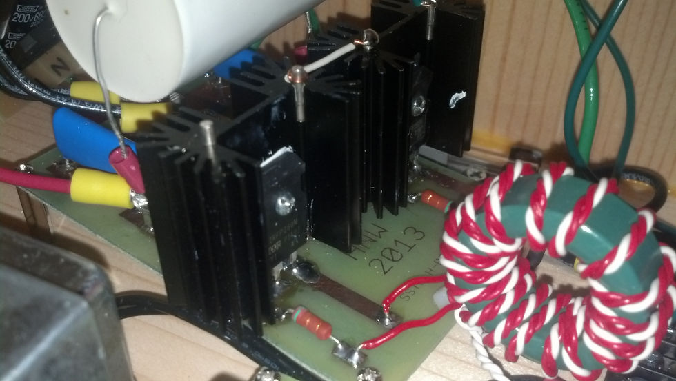
Here are two photos of the half-bridge Section. I am very happy with this layout as it works very reliably and is somewhat compact. The GDT secondarys are terminated directly to the circuit board and kept as short as possible. The core I used for the GDT is a green epoxy coated type 77 ferrite core by Fair-Rite Products Corp.
Dimensions (mm) = 36.8 x 22 x 13.7
Specific Inductance (AL) = 2400 +25% -30%
Initial Permeability (ui) = 2000
Manufacturers Product Code = 5977002721
Type 77 ferrite cores by Fair-Rite are probably the most popular and commonly used core for GDT's and CT's in small to medium powered SSTC/DRSSTC's. They can even be used in higher power systems as long as the gate signals have minimal overshoots, flat tops and bottoms, and fast rise/fall times under 200ns (nanoseconds) or so.
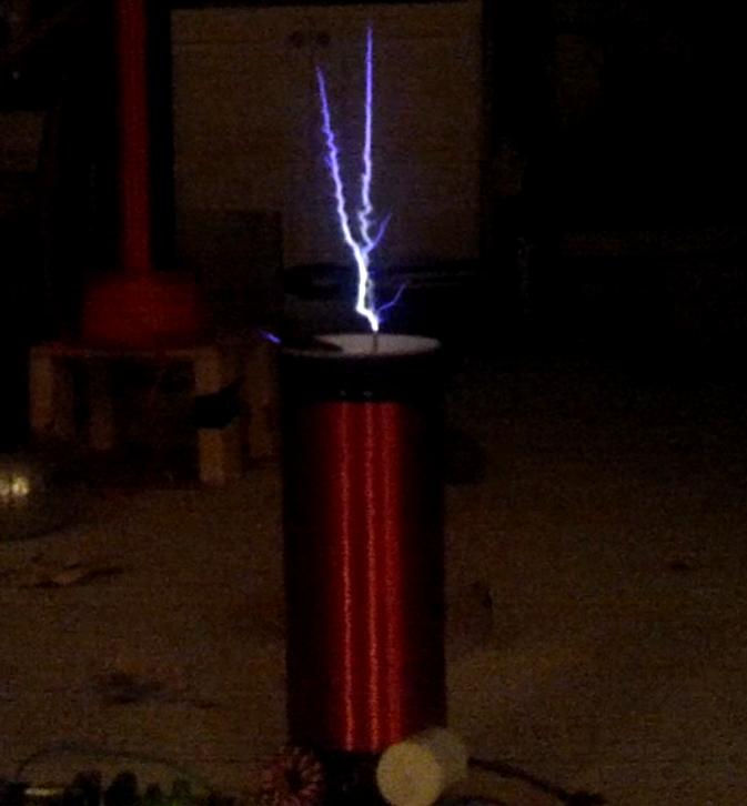
Below are photos of the burst mode. These are those spectacular thick sword-like sparks that are commonly seen in VTTC's (vacuum tube tesla coils) and QCWDRSSTC's (quasi continuous wave double resonant solid state tesla coil). I was very pleased with the results. This system only uses a half bridge topology and yet its exceeding the performance of my SSTC2 and SSTC1. The sparks generated by the burst mode are much longer then regular interruption. In these photos they easily exceed 8-10". Max spark length is to be determined.


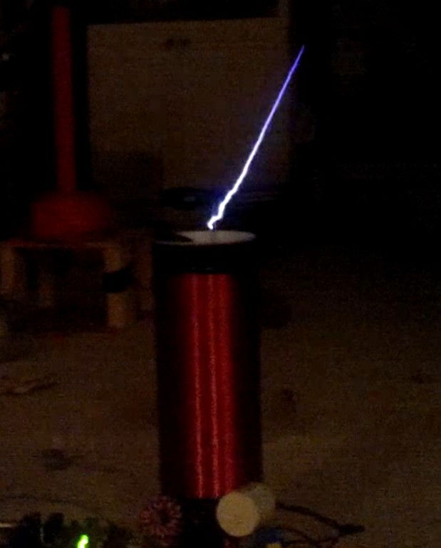


Below are photos of regular interruption. These are thin bushy sparks commonly seen in low to medium power SSTC's. I suspect that the spark length in these photos are no longer than 6".


And Finally, A video of operation