Harrison Wieting
PHYSICS ENTHUSIAST
SSTC1
Specifications
Secondary: 20" winding of 24AWG on 4.5" OD PVC form.
Primary: 5 turns of 16AWG stranded insulated wire tightly wrapped at the bottom of the secondary windings
Toroid: 4.5" OD 90 degree PVC elbows connected together
Feedback: Secondary feedback using an antenna
Power Electronics: 130V from the variac, full-wave rectified and smoothed by a 560uf capacitor.
Bridge: half-bridge of IRFP260N mosfets with 5ohm gate resistors
Control Electronics: On-board 555 based interrupter with UCC mosfet driver's
Grounding: Secondary is grounded to a 4' steel rod staked all the way into the ground, this worked very well. Ideally 6-8' grounding rod would be used, but because the soil where I live becomes solid rock and clay at about 4', I was limited to that depth.
Spark Length: 7.5" max
This is the first tesla coil I ever built. It is based from Steve Ward's Mini SSTC5, a well known and great tesla coil for beginners. I started this project in August of 2012, long before I made this site which is why I don't have very detailed specs on this system. This tesla coil system was very reliable and ultimately served as a modifiable system. As my knowledge of solid state tesla coils grew, I made many changes and improvements to this system and in the end, it turned into scrap for future coils.
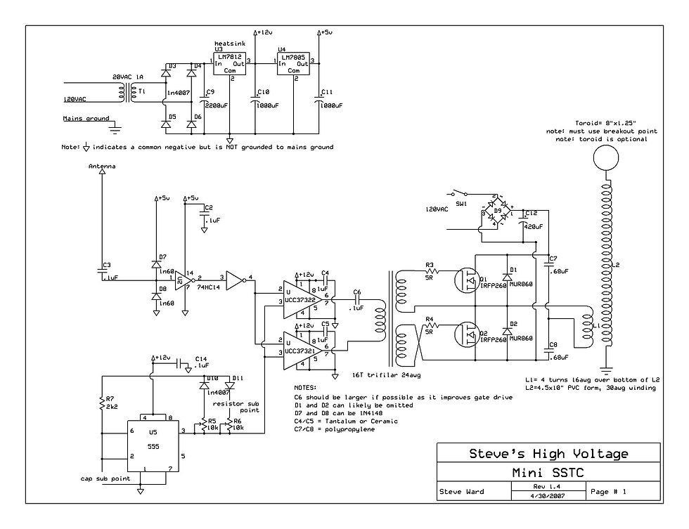
Schematic
This is a very basic design. This sstc is driven by one inverting and one non-inverting mosfet driver by Texas Instruments, powered by 12V. It uses an antenna and a hex inverter for secondary feedback which is fed right to the IN of the UCC mosfet driver's. A simple 555 based interrupter is used to enable the mosfet drivers. Basically, the interrupter sends a square wave signal to the mosfets which get the oscillations going in the primary. The antenna then picks up the signal from the secondary, gets clamped by a pair of diodes, and squared up by the hex inverter. This is such a reliable system because it is always in tune! This is called forced resonance. We are forcing the primary to resonate at the same frequency as the secondary. Still, you have to be careful with how many turns you have on the primary because you can overheat the mosfets or not get very good output from the secondary. The best way to determine this is to start with about 6 turns and monitor the electronics, removing one turn at a time until you achieve best performance without the mosfets overheating.

Control Electronics
Here you see the low voltage power supply, feedback circuit, and interrupter. Both regulators are on a heatsink that I pulled from an old PSU. The interrupter is on the far left with two thumbwheel potentiometers. You will have to click the image to see them. Last we have the antenna and hex inverter as the feedback circuit.

Gate Drive Circuit
This large red and white thing is the GDT (Gate Drive Transformer). It is 16 turns of 20AWG wound trifilar on a ferrite core. Due to my lack of knowledge in electronics at the time, I had bought some random ferrite core not carefully looking at the datasheet. As it turns out, this core was a horrible choice and I am surprised that I got any results at all. At the time, if I had known more about what type of core to use, the end results would probably have been much better. Anyways, The two mosfet drivers are on the lower right. In my system, I used a .47uF film capacitor for the DC blocking cap because it improves gate drive. The mosfets are seen on the black heatsinks in the background. Don't forget your silicon thermal pads!

Above is my setup, quite as expected being a first SSTC! I've seen worse, though! And finally on the right is the secondary coil. I believe I used 24 AWG, wound on 4.5 outer diameter PVC and enameled. Toroid consists of four 90 degree PVC elbows put together, sanded, smoothed, enameled, and aluminum taped. Surprisingly this turned out to be a decent quality resonator which I continued to use with later builds. I've made a minor change to it by adding a PVC endcap covered with aluminum tape to the top so that I can easily set the toroid on. Below are a few videos of operation.
Note: This system has a very strong electric field and will easily illuminate fluorescent tubes several feet away, as seen in the bottom left video with a 48" black light. Also, don't get your expensive smart phone's and digital camera's too close! Your smartphone may lose functionality or behave oddly when the tesla coil is running. I've had similar experiences with nearby laptops too. Efficient grounding and/or faraday caging, will help to keep this problem at a minimum.
