Harrison Wieting
PHYSICS ENTHUSIAST
DRSSTC2
(Dual Resonant Solid State Tesla Coil)
4-19-13 I've been thinking about a more powerful coil for a while now. I've just begun designing the parameters for this coil about a week ago. All parts except for the GDT's have been gathered. The new UD 2.5 was soldered today! The Secondary has been prepped for winding. Primary is already done. Basically, I wanted to build a powerful tesla coil with more spectacular performance than my DRSSTC1 but at a fraction of the cost. Below are some teasers of what I have compiled for this build. Note that the parameters seen in JavaTC are just a rough idea of the parameters. Actual parameters may be different. Click on the images for a closer look and description.
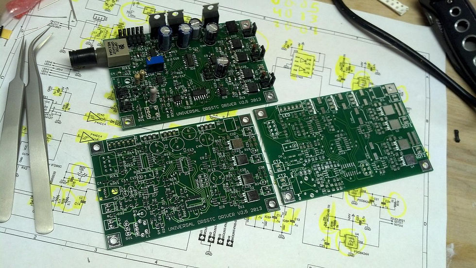
The new UD 2.5 special thanks to Steve Ward and Eric Goodchild. on the right is the older UD 2.1b
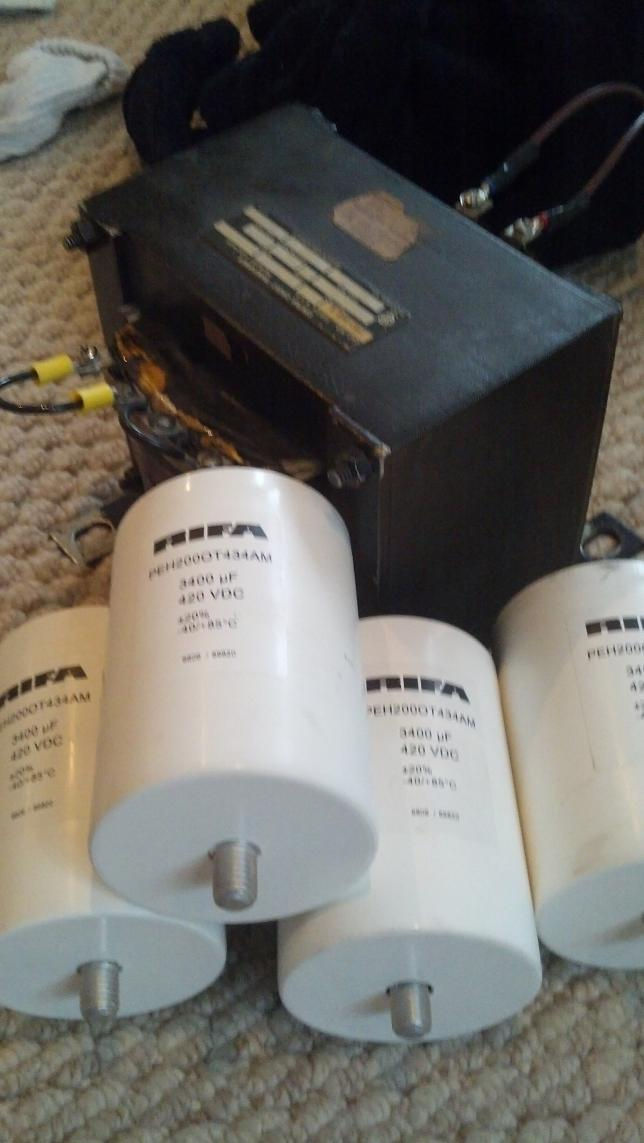
120/240 Step up transformer with RIFA DC Bus Caps. Lots of voltage!!!

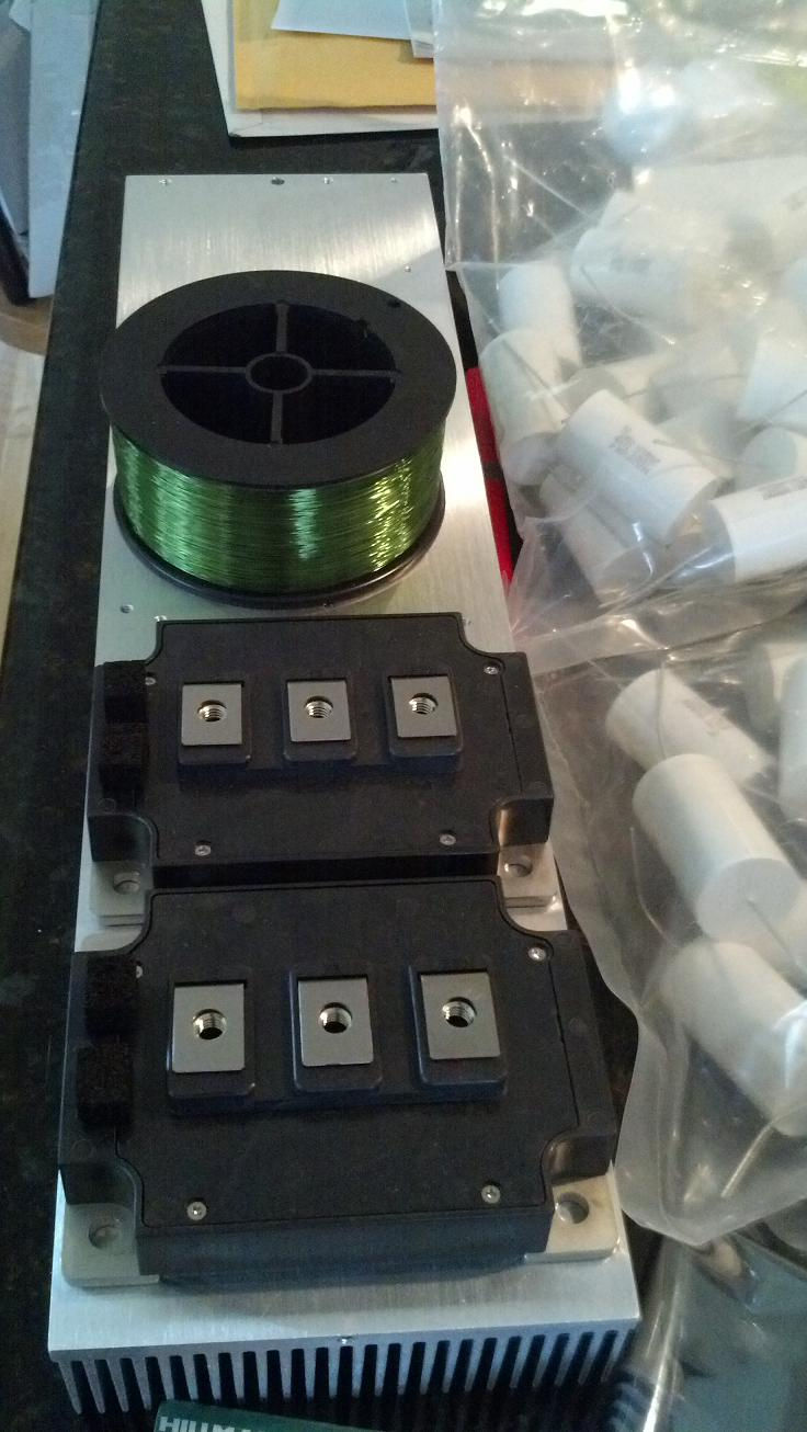
Green magnet wire, large CM dual modules, large heatsink, and big bag of CDE 942C caps.

Prepping the secondary for winding
4-30-13 The construction and preliminary troubleshooting has been completed since my last update. This would include the entire wiring of the system, completed secondary and dual toroid system, testing of the power supply, scoping the bridge output and adjusting the phase lead, so on and so forth. This build really reflects the learning experience and troubles that I endured in building my DRSSTC1. First of all, I started the DRSSTC1 build with zero knowledge of how a double resonant system works as well as all the relatively sophisticated circuits within the driver. Building the DRSSTC1 took about 7 months to turn a final working Tesla coil. Throughout that build I extensively researched and learned how the coil operates, a bit of design theory, and understanding of the driver circuitry. I've come to find that even having the most basic of understanding will make the biggest difference in getting the coil to operate properly. So all-in-all, once parts were gathered and I finished my design parameters, it took me a week at most to complete this entire build. 7 months to 1 week is a huge accomplishment! However, at this point, my new DRSSTC2 has yet to be powered up in full. Last night I went for first light and although I did get an output, I made a major miscalculation in my primary windings and thus I was tuned VERY low. This gave me very startling output sparks that were pretty weak. More specifically, I accidentally used the inner radius instead of the inner diameter of the primary when doing LC frequency calculations, so where I thought I was tapped at resonance was actually about 20kHz or so too low! Thank god these brick IGBT's can take abuse! So I've changed the primary tuning and look forward to doing more tests tonight. I also discovered a cold solder connection in my grounding of the secondary, and have added a grounded shielding enclosure partially around the base to prtoect the electronics from high voltage strikes. When I tested last night, I only input an average of 280VDC on the bridge and was already getting about 2.5' sparks and this was tuned way off! I cant wait to see what 700V tuned properly will give me! Below are some more recent construction and troubleshooting photos. The JavaTC information is now more accurate to my current system to date with the exception of the secondary frequency which is actually 68kHz, not 62.

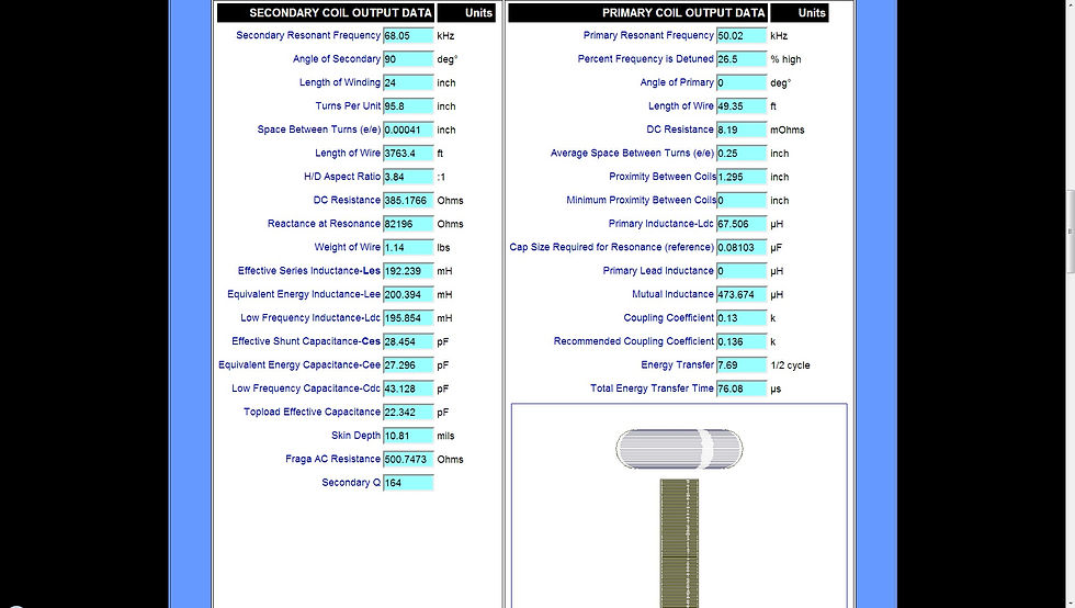
actual parameters as of 4-30-13
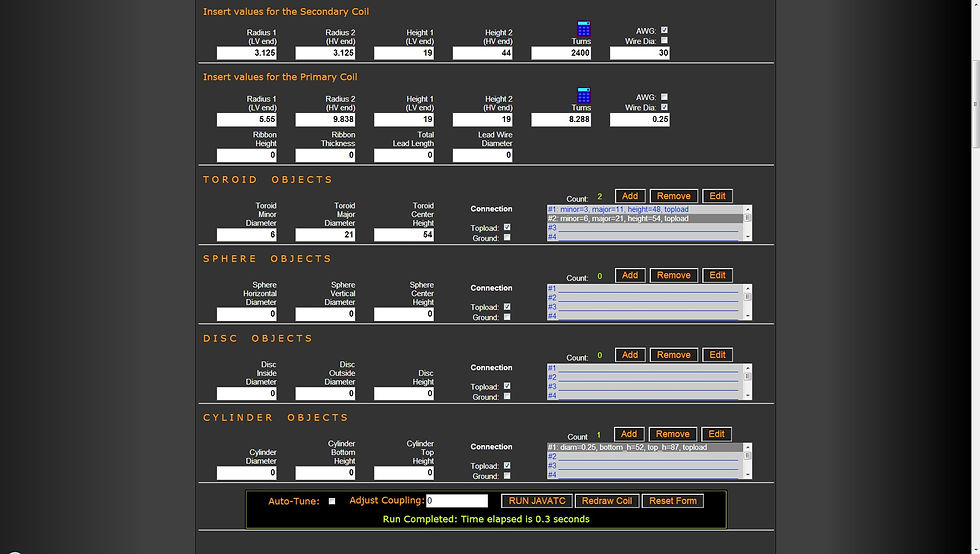
actual parameters as of 4-30-13


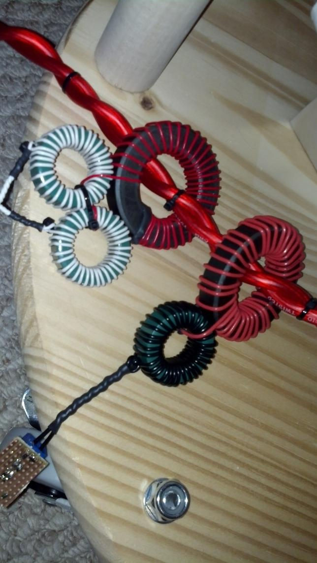
The primary, secondary, and toroids.

.18uF 10kV

Two Dual CM400 modules on an H-Bridge configuration. This is my first tesla coil build using large brick IGBT's. The conductors are made from 1/8" thick aluminum bars which I cut, drilled, and tapped myself. This is my first and best attempt at a low inductance layout. The snubbers are brand new MKP type 2uF 1kV polypropylene caps bolted directly to the IGBT terminals.

Such a mess. I admit, this is not impressive. Once I get some initial sparks, I will try and clear this wiring up a bit.

I could have done a better job with contacting the GDT's to the gates and emitters. Gate resistors are 1.1ohm. I found that gate resistors are not really necessary but must be used with GDT's. If I ever get a hold of less than 1ohm 2W resistors I will try them.
Great looking waveform on the GDT secondaries. Note that this is with the secondary's not yet connected to the IGBT's
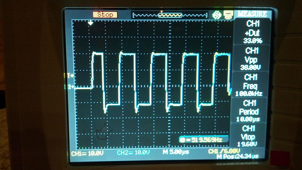
Best looking gate waveform I've ever seen!
My heavy Duty CT's. the one on the right is for current measurements only, while the one on the left with the two smaller fair-rite 77 cores are for the feedback and OCD. These are 1:33:33 cascaded.

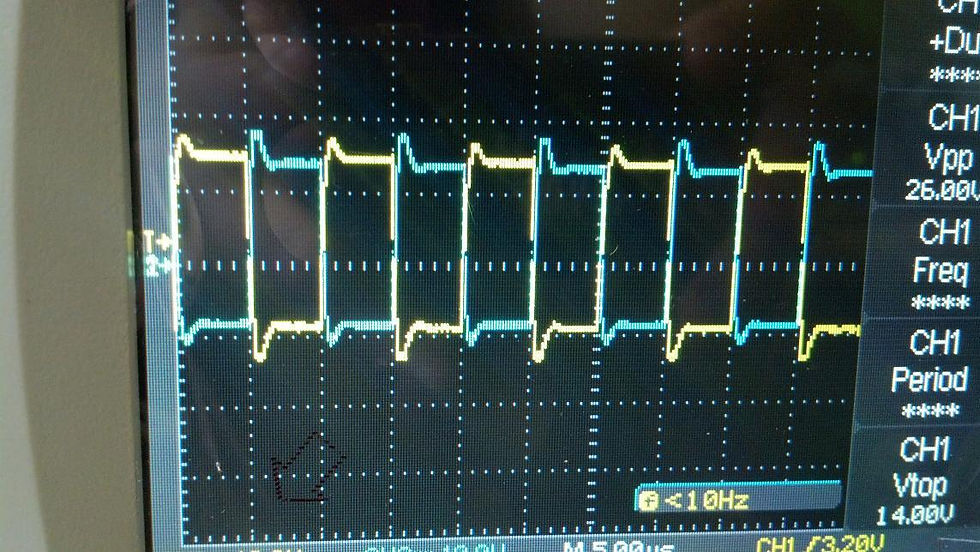
Differential Measurement of the bridge output which was useful when calibrating and learning about proper phase lead.


This is the best I could adjust the phase lead. This is also on the third cycle. The first cycle will always have some ringing, it is inevitable without adding some complex circuitry to the feedback network. Also as voltage and current increases, the ringing will slightly diminish.
5-10-13 Two nights ago I tuned the coil better and got great performance! This coil has great potential. I recently had a 220V 30A line installed just for Tesla Coils! Here in the U.S., a 220V breaker is just two 120V lines run 180 degrees out of phase, so it is a double breaker and single phase instead of 3-phase. I have yet to make a ballast for this line but I can't wait to get it hooked up to this coil. Right now my power input consists of a regular 120V 15A line -> 140VAC 1.4kVA autotransformer -> 240/120 step down transformer wired in reverse -> rectified DC voltage doubler for a maximum of 760VDC. This setup is just fine for this application with the exception of one limiting factor: my variac is only 10A rated. This is a problem because this coil wants more than 10A and it smokes 10A fuses like crack! So that is why I cant wait to get this system running off of the 220V 30A line and get the power I need. This will also be better so I can eliminate having to use a step up transformer that weighs a ton!
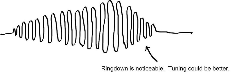
Anyways, this system is a medium-high impedance system. Z=12ohms. After talking a bit to Eric Goodchild, a Tesla coil pro, I've concluded that higher impedance systems give better overall performance especially for larger DRSSTC's powered by large IGBT brick modules. In short, this is because longer primary cycles will have less peak currents but with the same overall energy, so all the parts of the system will perform better. To quote him directly, he said "Think about a QCW they don't need very much peak tank current to make amazingly long sparks, it's all about the PW length." Furthermore, I observed that the primary current waveform envelope changes as I increase the pulse width. This is more obvious when you think about the change in peak current as the number of cycles change. Therefore the primary must be tuned optimally to compensate for this change in envelope. I have drawn up some sketches of the primary current envelope to illustrate this.
Above you can see that there are plenty of cycles, a nice long pulse, with noticeable ringdown. We must tune the primary to eliminate this ringdown. If you see ringdown, its not a bad thing. It just means you should probably tune the primary slightly lower. Fine tuning really plays a big role. I usually tap the primary in increments of 1/8 turns until I fine the best spot. Its amazing how much just a few centimeters of tuning can make a difference of several inches to the spark length.
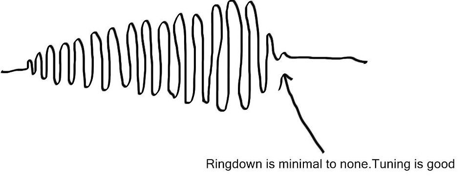
Above you can see that the ringdown has now diminished. This is a good tuning spot. Tapping in smaller increments might help to completely diminish the ringdown, but regardless, your max spark length will be right about here.
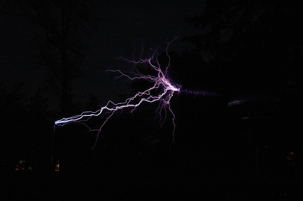
So overall that is how I had to mess with the tuning as I increased the pulse width to 225uS. At only 400VDC out of a possible 760VDC I was able to get five to six foot sparks at optimal tuning point. Also, i'll note that I was not using the step up transformer this time, I was just rectifying 140VAC to get a maximum of 400VDC. The reason I was not using the step up transformer is as stated before, I was blowing 10A fuses at about 3.5-4kW so thus there is no reason to use the step up transformer as it will not allow me anymore power. I can't wait to see how long the sparks will be when I can utilize +700VDC! Seven or eight foot sparks, maybe even nine? Who knows...
Below are a few spark photos from two nights ago. Click on them to see full resolution.


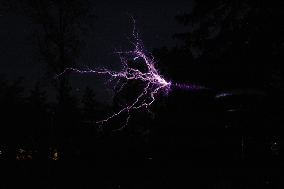


6-3-13 New record spark length of 74 inches (6feet 2inches)!!! I made a change to the toroid in efforts to reduce primary currents. All I did was make a much larger double toroid system and a much longer breakout point. The breakout point is thick 1/8" aluminum bar 6ft in length versus the 3ft 1/4" cylindrical rod I used before. The resonant frequency is now roughly 58kHz. The reason for the long breakout point was to try and keep the sparks well away from the strike ring and primary, as well as add a little bit of capacitance to the topload. I also put together a new power transformer that runs off of my 220V 30A outlet! Very excited to be using that now. I ordered an open type variac from the United Kingdom. It is a 0-280VAC 28A rated autotransformer made in India by a company called Ravistat. It seems to be of excellent quality and tests to spec. Compared to the USA made products such as Powerstat or Superior Electric, the Ravistat beats all for the price. Of course I enclosed the autotransformer and added a few voltmeters and ammeters as well as a 30A DPST switch, 30A outlet, and 240VAC neon pilot light. It's an awesome transformer and I'll upload a few photos of that later. Also, I am now running with some 15A fuses and have yet to blow one. I have started experimenting with my MIDI modulator and have got it to work, but I need to mess with the PW settings to get the spark length right. I am in a good spot for tuning right now, but I do see a see a slight notch at the end of the pulse so some fine tuning is in order. Primary current sits between 950A-1000A. Below is a short video of operation. I was wrong when I said the primary is about 15kHz detuned. It is actually 11kHz (20%) detuned.