Harrison Wieting
PHYSICS ENTHUSIAST
SSTC2
Specifications
Secondary: 20" winding of 24AWG on 4.5" OD PVC form.
Primary: 6 turns of 14AWG stranded insulated wire wrapped with about 3/4" spacing between turns around a plastic pot form that has an outer diameter of about 8"
Toroid: 4.5" OD 90 degree PVC elbows connected together
Feedback: Secondary feedback using an antenna
Power Electronics: 130V from the variac, half-wave rectified and smoothed by a 10uF 400V CDE
Bridge: Full-bridge of IRFP260N mosfets with 5ohm gate resistors
Control Electronics: On-board 555 based interrupter with two pairs of UCC mosfet driver's in parallel with two GDT's
Grounding: Secondary is grounded to mains earth
Spark Length: 14" max
I started this SSTC sometime around October of 2012. This build of course stemmed from modifying my SSTC1 and there really wasn't much 'building' to do. There are three major differences here. That is a new primary, use of a full bridge configuration, and half-wave rectification of the DC power supply to the bridge. This system had poor performance. I expected much greater output, but looking back on things, the full-bridge was very sloppy, GDT cores were not the right type, and driver circuitry was poorly designed.
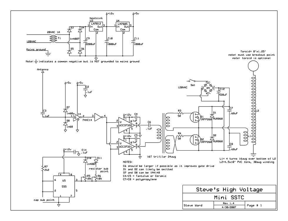

Schematic
I used the same overall design for this system as in the SSTC1. All that is different in regards to the control circuit is the addition of two more UCC mosfet drivers. I also used a 9V regulator in place of the 5V, which I later learned was a big NO NO. I fried a few UCC chips because the enable voltage was +9V and occasionally exceeded that due to poor design layout. Other's have had no problem's with using 9V, so experiment at your own risk.
This is the bridge topology I used. Very standard full-bridge configuration. I also used two GDT's instead of one. This is necessary because two GDT's can deliver more power than one, among other things. And once again, the cores I chose were not the right type.

Control Electronics
For this build I wanted to fit everything on the same circuit board and keep the whole circuit small so that it would not be so bulky and ugly like the last one. In this picture I have two of four UCC chips in their sockets, probably for testing. Same with the hex inverter. You will also notice that I ignorantly used a polarized electrolytic capacitor for DC blocking of the gate drivers. This still worked, but you do not want to use this because electrolytics HATE reverse voltage. Ideally, a bipolar chip cap should be used. Other good choices are film and multilayer ceramic. Some people use tantalum caps, which is okay for some low power tesla coil systems. I would not do this for Higher powered SSTC's and DRSSTC's because they also do not respond well to reverse voltage. I have personally had many problems with tantalum capacitors. Unfortunately I do not have any photos of the full-bridge.

The Coil
I used The same 20" secondary and toroid in this build. I did this because it saved a lot of time and money. The new primary can be seen around it wrapped in orange electrical tape to keep it tight against the form. I also chopped up the base to make it smaller and easier to set up.
Below is a short video of operation.